0086-551-67295053
 info@bransensor.com
 Mon-Sat: 8:30-18:00
 Hefei City, Anhui Province, China


 0086-551-67295053
info@bransensor.com
Mon-Sat: 8:30-18:00
Hefei City, Anhui Province, China
0086-551-67295053
info@bransensor.com
Mon-Sat: 8:30-18:00
Hefei City, Anhui Province, China
 Force Sensor
 Load Cell
 Torque Force Sensor
 Multi-axis Force Sensor
 Piezoelectric Force Sensor

The steps involved in manufacturing load cells include:
1. Purchase metal and test material received
2. Machine metal into the sensing element shape
3. Heat treat the sensing element
4. Apply strain gages and wire them in a Wheatstone Bridge
5. Measure bridge unbalance and apply correction resistance
6. Verify bridge balance
7. Measure temperature effect and apply correction
8. Verify that temperature effects are within limits
9. Verify that creep, linearity, and Hysteresis are within specifications
10. Measure rated output and apply correction
11. Verify that rated output is within specification limits
12. Seal the load cell from the environment
13. Perform final bridge readings and zero balance, carefully pack and ship
Each of these steps will be discussed in appropriate detail below:
1. Purchase metal and test material received
We think of metal as simply metal but there are many different alloys available on the market. Each alloy has different results when used in sensing element design. There is a choice of quality levels of metal available on the market today. The quality level required depends on its use. Load cells, sensors, require a high level of quality. Different mills deliver varying alloy compositions within relatively broad standard limits. The subsequent rolling, straightening, annealing, and pickling processes can vary, too. Within a single mill, the manufacturing can vary and affect the consistency from lot to lot. Additionally, the variance in process control at each mill results in the reality that metal from one mill will yield considerably different results than metal from another, and metal from one mill is not guaranteed to remain at a consistent level of quality and performance. To remove, or greatly reduce, these variables, a quality load cell manufacturer must invest in people and time to investigate different alloys, potential metal vendors, test material and continuously monitor successful vendor's quality. This represents an overhead cost to the manufacturer and a higher material cost for higher quality metal.
2. Machine metal into the sensing element shape
The mechanical design of the sensing element structure governs the precision of the measurement. A good design can be largely immune to typical stray forces where another might be affected. The ultimate overload strength of the load cell is determined by the mechanical design and yet can be in conflict with the sensitivity of the sensor measurement. Mechanical designs with uniform stress distribution return considerably better results than those with gradients of stress through the gage area. Those providers committed to optimum designs must invest in talented and experienced engineers to design and test top performing load cells.
3. Heat treat the sensing element to obtain prescribed strength, toughness and grain structure
You may be familiar with heat treating metal to make it stronger but in the manufacture of load cells, the sensing element is carefully heat treated to achieve an optimum combination of yield strength, toughness, creep, change in creep with temperature and Hysteresis. A properly heat-treated sensing element will undergo up to four separate processes in controlled atmospheres and with the use of expensive equipment. The heat-treating process is proprietary to each load cell manufacturer. Quality load cell manufacturers must invest time in perfecting the heat-treating process for their designs and then monitor that process for consistent practice. Those who make large investments in their own heat-treating ovens have rapid feedback of problems and ultimate control over the proper heat-treating process being followed on each load cell sensing element.
4. Apply strain gages and wire them in a Wheatstone Bridge
Designing and manufacturing strain gages are disciplines in themselves resulting in different gages having a variety of performance levels. Gage design and application can affect linearity, creep, Hysteresis, temperature effects on zero and span. Load cell providers who design and produce their own gages have ultimate control over the fit of the gage design with the load cell sensing element mechanical design. For example, some manufacturers design gages with varying amounts of negative Hysteresis used to offset positive Hysteresis in the sensing element material. Providers who buy off-the-shelf gages do not benefit from the ability to design a gage specifically for each load cell designed. Additionally, the application of the gage must be performed in a clean environment by people trained and equipped with the proper tools to do a precision job. Those performing this tedious and precise job must be carefully selected and trained. Precision fixtures must be designed to properly locate the strain gages, since the ultimate performance of the load cell is no better than the precision of the strain gage location. Quality load cell manufacturers must invest in engineers who select or design, and test gages for optimum results and in equipment and training of employees who apply the gages.
5. Measure bridge unbalance and apply correction resistance
Resistors must be added to balance the Wheatstone Bridge so that the "no load" output of the load cell is within prescribed limits an unbalanced bridge means that you would measure different levels of output from different load cells with the same load applied.
6. Verify bridge balance
A step often skipped, the bridge balance must be checked to verify proper adjustment in step 5.
7. Measure temperature effect and apply correction
Each load cell must be temperature compensated for effects of temperature on zero and span. An uncompensated load cell will vary its output as temperature changes. The temperature effect on span is consistent with each lot of metal and production as long as each step leading up to this test is controlled. Temperature effect on zero varies from load cell to load cell and therefore must be measured individually and corrected by adding temperature compensation elements or resistors.
8. Verify that temperature effects are within limits
Most of the time the compensation added in step seven is sufficient, causing many providers to skip this verification step but leaving the user wide open to temperature effected load cells. Verification is important since there are finite differences between the temperature characteristics of the individual strain gages and the temperature compensating components which must be "compensated out" in precision load cells. For precision load cells, the temperature compensation on zero should be verified on a 100 percent basis. The temperature compensation on span should be verified on a sample basis.
9. Verify that creep, linearity and Hysteresis are within specifications
Creep, linearity and Hysteresis have already been determined by design and process control in the prior steps. Many providers sample test the production run to spot check the performance. Quality providers conduct 100% verification to ensure that each and every load cell has been produced within advertised specifications. This 100% testing is important since there are finite differences between the temperature characteristics of the individual strain gages and temperature compensating elements which must be "compensated out" for precision load cells.
10. Measure rated output and apply correction
The rated output sensitivity of the load cell must be measured and adjusted to be within a tight tolerance for each unit produced. This is often referred to as "matching the mV/V output" of the load cell to others of the same model produced. The process of matching load cell outputs involves measuring the output and applying correction resistors. The objective is to have the same level of output change for a given load applied regardless of which load cell in the system supports the weight. Most manufacturers attempt to match mV/V of each load cell to within a tolerance. The tightness of the tolerance varies between manufacturers and only two manufacturers (to our knowledge) match mV/V/ohm output characteristics of their load cells and only one manufacturer matches both mV/V and mV/V/ohm characteristics.
11. Verify that rated output is within specification
It is important that the load cell manufacturer verifies that the calibration resistance added has, in fact, properly adjusted the rated output to within prescribed tolerances and that no problems have been introduced as a result of making electrical adjustments.
In steps 5,7 and 10 resistance has been added to adjust for bridge balance, temperature effect on zero and output sensitivity. In these steps the resistance added should be of the high precision type, e.g. 10 parts per million (ppm), as opposed to lower cost and readily available 50 ppm resistors.
In steps 6, 8 and 11 these corrections have been verified to be within spec and that no new problems have been introduced as a result of the assembler or technician physically adding resistance. There is a lot of time spent in these measurement, correction and verification stages to meet performance specifications that usually are not checked by the customer. Quality load cell manufacturers must develop sound manufacturing processes and monitor themselves to make sure all steps are followed. Without an outside checking function and with tremendous price pressure from the market, it is tempting for some manufacturers to spend less time in these adjustment and verification stages. Only those manufacturers with the strongest desire to uphold quality will continue to hold themselves accountable for proper and thorough testing and performance. Questions that should be asked when evaluating a load cell manufacturer include:
• How many specifications are verified on each load cell produced versus quoting
typical performance?
• What data is recorded on the specification sheet? (measured or typical?)
• Who monitors the results of the testing?
• Are the test technicians given conflicting directions or requirements? (Accuracy of
measurement versus more units produced in a shift)
• Are test instruments regularly checked and matched with each other?
Performance parameters that are not guaranteed to be consistent from one
manufactured load cell to the next and therefore should command 100% production
testing include:
Ø Creep
Ø Linearity
Ø Hysteresis
Ø Temperature effect on zero
Ø Bridge balance
Ø Bridge input and output resistance
Ø Insulation resistance, bridge to element, at 50 VDC
Ø Output Sensitivity
12. Seal the load cell from the environment
One of the most misunderstood specifications for load cells is the level of sealing. Load cells must have good sealing, therefore protection from the environment, to yield longevity of the load cell and consistency of the measurement. Moisture in the load cell or the cable will quickly result in erroneous readings. Moisture entering the gauged cavity of the load cell is absorbed by the organic strain gage backing causing relaxation of residual stress, lower strain transmission and lower insulation resistance to the element. Anyone of these factors will cause zero drift and span changes. Other foreign materials entering the gauged cavity may cause similar effects and even corrosion of the strain gages and associated connections. Load cell life is shortened, as a result.
One source of confusion is created by the load cell manufacturers themselves who mislead consumers as to the level of seal provided. A strong example of this is misuse the term "Hermetic Seal". According to Webster's Dictionary "hermetically", as in hermetically sealed, means "A vessel or tube is hermetically sealed when it is closed completely against the passage of air or other fluid by fusing the extremity; -- sometimes less properly applied to any air-tight closure."
Many manufacturers claim hermetic "sealing" and point to welded caps over the gauged area but fail to discuss the sealing at the cable entry of the load cell and the subsequent passages of the wires to the gauged area. Very few, maybe just one, manufacturer(s) actually provides a load cell closed completely against the passage of air, gas or fluids by fusing the extremity and is prepared to discuss the level of the seal effectiveness by testing. The only way to be certain that a load cell has been properly hermetically sealed at the gauged cavity and at the cable entry is to perform a helium leak test in those areas. That is done be connecting the load cell to a mass spectrometer and evacuating it to a "hard" vacuum. A source of helium gas streaming through a small needle is brought close to the welded joints and if there is a leak the helium enters the load cell and is detected by the mass spectrometer. The leakage rate is measured in units of cubic centimeters of air per second. A water vapor molecule will slip through an opening which exhibits a leakage rate of 10 exp-6 cubic centimeters of air per second. One load cell manufacturer requires a leakage rate of lower than 3 exp-8 for acceptance, one thirtieth of that required to admit a water vapor molecule. While the load cell is evacuated it is good practice to back fill it with dry nitrogen when the leakage test has been completed. This ensures a good, dry, inert environment for the strain gages and associated circuitry.
For applications not requiring hermetic sealing, potted load cells can be sufficient. In all cases the manufacturer should be talking from a point of knowledge about the seal and not quoting specifications typically requested or those found in competitor's literature.
12. Perform final bridge readings and zero balance, carefully pack and ship
One final check is in order to make sure that the product performs as specified. Specifically, it is a good practice to make final electrical bridge readings, insulation resistance to element and zero unbalance.

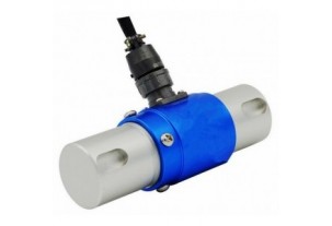

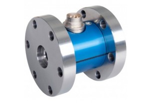
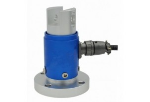
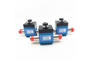
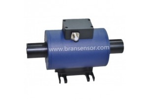
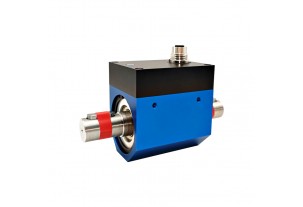
Reaction Torque Sensor With Shaft to Shaft Torque force measurement transducer (BTQ-402)
Read more +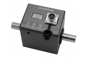
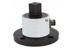
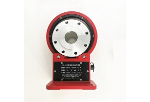
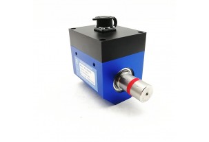
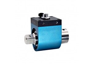
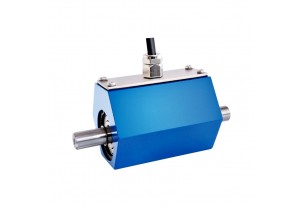
Non-contact Shaft to Shaft Rotary Torque Sensor with Build-in Display to Show Torque, Speed and Power (BTQ-408RTS2)
Read more +
 0086-551-67295053
 info@bransensor.com
 Mon-Sat: 8:30-18:00
 Hefei City, Anhui Province, China


Copyright © 2018 BRANS Measuring & Controlling Technology Co. Ltd


 Pусский
  Español
 ABOUT US