0086-551-67295053
 info@bransensor.com
 Mon-Sat: 8:30-18:00
 Hefei City, Anhui Province, China


 0086-551-67295053
info@bransensor.com
Mon-Sat: 8:30-18:00
Hefei City, Anhui Province, China
0086-551-67295053
info@bransensor.com
Mon-Sat: 8:30-18:00
Hefei City, Anhui Province, China
 Force Sensor
 Load Cell
 Torque Force Sensor
 Multi-axis Force Sensor
 Piezoelectric Force Sensor

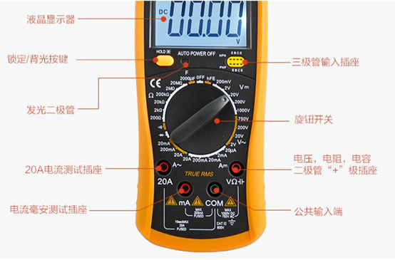
Set the multimeter in DC millivolts and connect the output wires of the load cell to the multimeter. Supply a voltage of 5V or 9V DC at the excitation leads and place a test weight on the load cell. The multimeter will register a change in voltage measured across the load cell’s output.
How to Test a Load Cell
To test a load cell before putting it to use, you’ll need a multimeter and a voltage source. Measure the resistance of the input and output leads of the load cell by setting up the multimeter in Ohms. Compare the measurement values with the calibration certificate from the manufacturer to see if they closely match each other. Similarly, check the load cell for accuracy by measuring the millivolts signal from the input leads. With no force applied to the load cell, the value should be zero. Apply a calibrated dead weight as specified in the calibration certificate and compare the values again.
How to Measure Load Cell Output
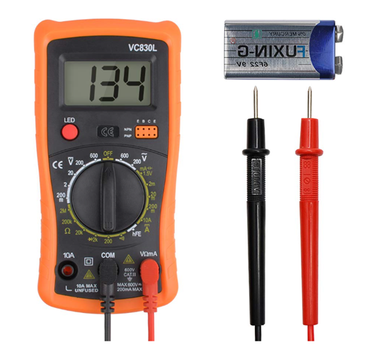
Load cell output is measured using a digital meter. The digital meter connects to the output of the load cell. It converts the digital signals produced by the load cell into readable digital values. You can also measure the output of a load cell using a multimeter. However, a multimeter will delete the output voltage in millivolts, and will not convert it into force or weight.
How to Check Load Cell Resistance
A load cell test is performed using a digital multimeter. The digital multimeter is connected between the positive signal wire and the negative signal wire of the load cell. The output between them should be equal or to a value specified in the datasheet. This is the test for load cell output resistance. Now check the signal between the positive excitation wire and the negative excitation wire. They should be equal. This is the test for input resistance.
Load Cell Value Fluctuation
Load cell values can fluctuate due to several reasons. From physical damage such as shock loading and overloading for a longer duration to environmental conditions such as temperature, moisture, water ingress, or corrosion, the load cell is likely to produce erroneous output. Measurement values will also fluctuate if the cables break or if there’s a short circuit. To check what is causing fluctuations in the load cell value, perform a visual check to identify the fault location. Perform a zero-balance check to identify if the strain gauge has undergone permanent deformation. An insulation resistance check can further help you identify if moisture is getting inside the load cell. Additionally, a bridge resistance check will determine if there’s a short circuit within the load cell.
Load Cell Zero Drift
Zero drift is the condition where zero measurements of the load cell change randomly under no-load conditions. It can also happen when the apparatus is loaded, and this phenomenon is called Drift. Several reasons such as mechanical errors, fluctuation in excitation voltage, and temperature variations could cause drift. To troubleshoot the load cell for zero drift, it is important to inspect the entire system.
Load Cell Negative Reading
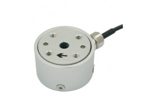
Load cell negative reading occurs when the load cell is in an incorrect orientation. If the load cell is upside down, it would produce negative readings under loading. There is usually an arrow on the load cell that shows the direction of loading. A Load cell used to measure tension will not reflect negative reading if installed upside down and will result in an erroneous reading. However, if the load cell is installed correctly and the readings are still negative, verify the wire connection according to the color code specified by the manufacturer.
Load Cell Overload
Every load cell comes with rated capacity. Loading the load cells beyond the rated value overloads the load cell. The telltale signs of load cell overload are inconsistent display reading, reading not coming back to zero even after the load is removed, the dramatic change of zero balance, etc. Shock overload is one of the most damaging among overloads. Here the weight on the load changes to a significant degree in a very short period. Most load cells endure some overload and this value is called Safe overload. Anything beyond that can lead to permanent damage.
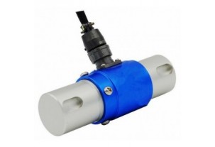

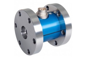
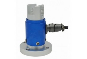
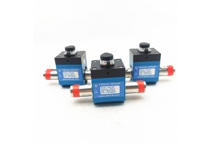
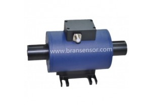
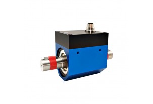
Reaction Torque Sensor With Shaft to Shaft Torque force measurement transducer (BTQ-402)
Read more +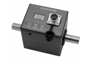
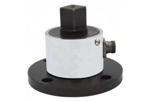
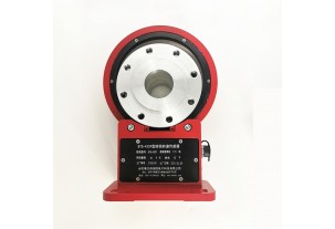
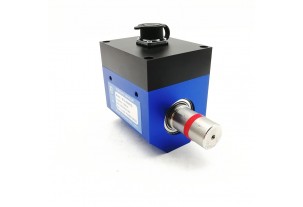
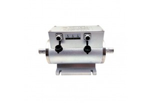
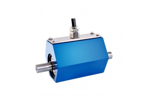
Non-contact Shaft to Shaft Rotary Torque Sensor with Build-in Display to Show Torque, Speed and Power (BTQ-408RTS2)
Read more +
 0086-551-67295053
 info@bransensor.com
 Mon-Sat: 8:30-18:00
 Hefei City, Anhui Province, China


Copyright © 2018 BRANS Measuring & Controlling Technology Co. Ltd


 Pусский
  Español
 ABOUT US