0086-551-67295053
 info@bransensor.com
 Mon-Sat: 8:30-18:00
 Hefei City, Anhui Province, China


 0086-551-67295053
info@bransensor.com
Mon-Sat: 8:30-18:00
Hefei City, Anhui Province, China
0086-551-67295053
info@bransensor.com
Mon-Sat: 8:30-18:00
Hefei City, Anhui Province, China
 Force Sensor
 Load Cell
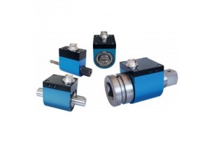
 Torque Force Sensor
 Multi-axis Force Sensor
 Piezoelectric Force Sensor

One of the most common applications is acquiring data from a load cell or any full-bridge type sensor such as a strain gauge bridge with an A/D board. It is also the least understood, and many users make simple wiring errors, causing excessive noise, and in extreme cases, damage to the sensor and instrument.
The first thing to remember when installing a load cell is that you must measure it with a DIFFERENTIAL input type, and not a SINGLE ENDED input type.
First, determine if your A/D device (your PLC, indicator, or DAS) can be configured as a differential input. Then, you must use a regulated power supply to provide excitation for your sensor.
If the power supply is noisy, or unregulated, then the sensor output will also be noisy or will drift. Some A/D boards have built in regulated power supplies; however, you may not be able to connect more that one or two sensors due to current limitations.
Plug-in boards usually provide a +5V and -5V connection, however, this is usually the computer’s PC power supply which is not suitable for bridge sensor excitation.
The best thing to do is to purchase a separate highly regulated power supply like this one that can handle the current for all of the sensors that need to be powered.
The following diagram will demonstrate the correct wiring configuration for a load cell to a differential input. Keep in mind that if more than one load sensor is connected to the same power supply, you only need to connect the ground screw to only ONE ground, otherwise, a ground loop may be created causing additional noise.
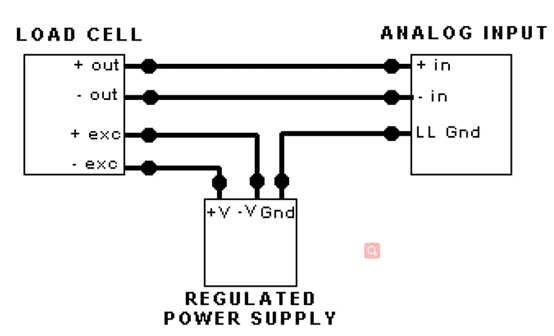
Also, make sure that the power supply is FLOATING, meaning that it is not already connected to another ground anywhere else.
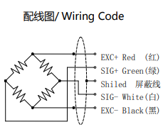
It is important to know the wire color codes for a given load cell to ensure that they are properly connected for accurate results. The color codes vary between manufacturer and the coding is usually provided on the load cell’s calibration certificate. It is important to follow the color coding as specified by the manufacturer. This will ensure proper wiring connections and avoid erratic output.
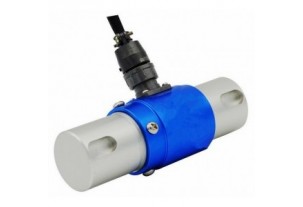

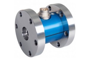
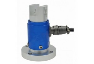
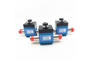
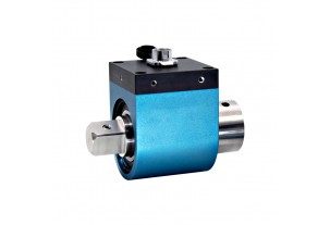
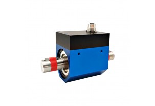
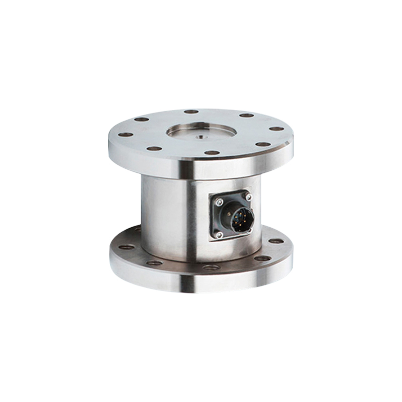
Reaction Torque Sensor With Shaft to Shaft Torque force measurement transducer (BTQ-402)
Read more +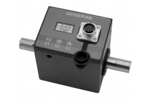
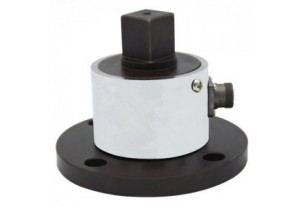
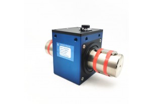
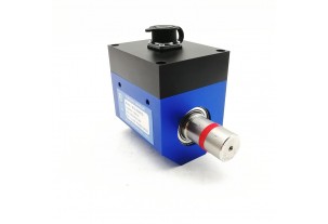
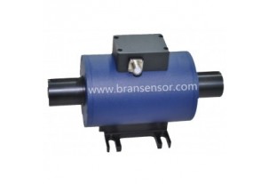
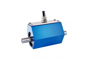
Non-contact Shaft to Shaft Rotary Torque Sensor with Build-in Display to Show Torque, Speed and Power (BTQ-408RTS2)
Read more +
 0086-551-67295053
 info@bransensor.com
 Mon-Sat: 8:30-18:00
 Hefei City, Anhui Province, China


Copyright © 2018 BRANS Measuring & Controlling Technology Co. Ltd


 Pусский
  Español
 ABOUT US