0086-551-67295053
 info@bransensor.com
 Mon-Sat: 8:30-18:00
 Hefei City, Anhui Province, China


 0086-551-67295053
info@bransensor.com
Mon-Sat: 8:30-18:00
Hefei City, Anhui Province, China
0086-551-67295053
info@bransensor.com
Mon-Sat: 8:30-18:00
Hefei City, Anhui Province, China
 Force Sensor
 Load Cell
 Torque Force Sensor
 Multi-axis Force Sensor
 Piezoelectric Force Sensor

How to mount a load cell?
Each load cell installation is unique as there are several types. Consult a structural engineer when your application requires very high accuracy, long-term stability, custom specifications, or when using in a varied R&D environment.
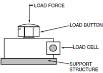
In order to gain precise weighing results, be sure to use specified load applications for load cells. Load cells have a specified load direction; do not apply side forces, bending or torsional movements on load cells. Inappropriate loading applications will risk reducing the life of load cells, plus distortion of correct measurement results.
Using a rigid design for the support structure of load cells in compressive loading applications is preferred to pliable designs to achieve even lowering of all supports that also distributes tension, and provides an even contact surface.
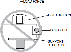
Mounting the load cells to the support structure and rigid base plate, ensures even load transfer from the base of the load cell to the support structure. This structure must also have the capacity to support the forces corresponding with the load. Mounting aids may be needed for compliance with load cell installation. Seek assistance from the design engineer to determine the weighting of individual disturbance possibilities. Special considerations for weighing tanks, thermal expansions, monitoring levels, and horizontal movements for certain tank shapes and support structures are required to avoid measurement distortions. Your load cell support structure may need end-stops to limit lateral deflection, and elastomeric bearings can also regulate heat between the tank and load cell. Also if your load cell requires self-centering, the design engineer may suggest a pendulum load cell that will automatically guide the super structure into its original position.
Specific Applications
Gas Turbine Engine/Rocket: High accuracy measurements of the volumetric flow of gas through the pipeline. The turbine rotor turns the rotor blades by gas flow into the meter, measuring gas velocity. The rotor blades pass a pickup coil, generating an electrical signal pulse. The pulse is equal to a specific volume of gas. Total volumetric flow is recorded by the number of pulses. Expression of flow rate is measured in actual cubic feet or actual cubic meters, (ACF/AM3).
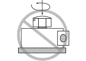
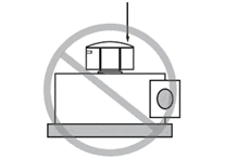
Bending or Torsional Moments Not Recommended
Engine Thrust Measurement:
This built-to-order combination torque and thrust reactionary and rotary load cell product is constructed in all stainless steel for long term reliability. Applications in industrial environments include safe overload of 150% of capacity, ultimate overload at 300% of capacity. Call engineering for specifics.
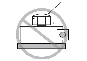
Side Forces Should be Avoided
Bin Weighing: To simplify load cell installations, use tank and bin weighing systems with capacities of up to 2500 pounds. Systems provide shock absorption for industrial installations and helps to prevent improper mounting, which can cause load cell damage. Make a complete four-point system with 4000-pound maximum capacity with heavy duty shear beam type load cells and tank and bin weighing system.
Process Control Systems: The wide range of process controllers include temperature controllers, ramp and soak controllers, dual-zone controllers, and bench-top style process controllers. Microprocessor based controllers come with various displays, wire RTDs, process voltage and current. They can connect directly to the Ethernet network featuring an embedded web server, downloadable data acquisition software.
High Load Fatigue Testing: Reduces time needed for troubleshooting scale systems, analyzes conditions of strain gage-based load cells in scale and industrial applications. Test load cells without disconnection, easy-to-read, clear screen messages. Provides essential data, like possible distortions from overloads, metals fatigue or shock loading, and possible ground faults or bridge resistance electrical problems.
Bridge Testing: Using a terminal block system with bridging and testing accessories across different clamping technologies reduces inventory and logistics costs. A modular terminal block design can be combined with different terminal block types or individually for application flexibility.
Considerations before installation
Types of Installations: In addition to typical installations of hydraulic, pneumatic, and strain gage types of load cells, BRANS customers often ask about bending beam load cells, shear beams, canister type, ring and pancake load cells, and button and washer type load cell installations. Some other more advanced types of load cell installations for specific uses include helical, fiber optic, and piezo-resistive types of load cell installations. Contact Brans for details on your specific load cell installation requirements.
Support Structure Must Contact Lower Outer
Load Orientation: Service technicians find the most common cause of accuracy problems with load measurements are incorrect load cell mounting which results in imprecise vertical loading that creates extraneous force errors. The loads must act precisely in the direction of the load cell.
Environment: Magnetic and electrical fields can sometimes create interference voltage within a measuring circuit. To ensure protection from EMC, place the load cell, connection cabling, and electronics in a shielded housing. Do not ground the indicator, load cell amplifier, and transducer more than once.
Framework of Structure: Protect the measurement cable using steel conduits. Use shielded, low-capacity measurement cables such as HBM cables. Avoid stray fields from motors, contact switches, and transformers. Using a rigid design for the support structure of load cells in compressive loading applications, preferred to pliable designs, to achieve even/balanced lowering of all supports that also distribute tension, and providing an even contact surface. Mounting load cells to the support structure, and rigid base plate, ensures even load transfer from the base of the load cell to the support structure. This structure must also have the capacity to support the forces corresponding with the load.
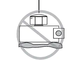
Flat and Clean Surface Required
Today’s mechanical scales can weigh loads of all kinds, from pharmaceuticals to tanks and shipping cars. Consistency of weight calculations and readings require the best weight balancing mechanism designs engineered to sense force, proper calibration, and maintenance. Depending on the output signals generated, we distinguish load cell designs according to weight detection, such as tension, compression, bending or shear, for example. Strain gauge load cells convert on acting loads into electrical signals. The change in pressure of internal filling fluid measures weight using force balancing devices in hydraulic load cell designs. Higher accuracy requirements can be achieved using multiple dampener chambers which also operate on the force balance concept with pneumatic load cell engineering.
How to connect four load cells?
In a four-load-cell system, each load cell must measure one-quarter of the total load. This type of configuration is more common in industrial scales. Here, each load cell is mounted at each corner of the platform.
The output terminals of all the four load cells are connected to a junction box, where signals from all the load cells are trimmed and combined into one single output. The junction box will make necessary adjustments whenever the location or orientation of the load changes. This final output is then sent to the strain indicator or a handheld display for final measurement.
How to check load cell working or not?
You can check if the load cell is working or not by verifying two aspects of the load cell – load cell resistance and the load cell voltage.
Load cell output resistance is measured between the positive and negative wires. The load cell input resistance is measured between the positive excitation wire and the negative excitation wire. In both cases, the value between the wires must be equal or similar to the datasheet provided with the load cell.
To measure the load cell voltage, connect the two wires to the amplifier. Now measure the response signal between the positive and negative signal wires while incrementing the load to see the corresponding signal increment.
Load cell verification procedure
Although load cells provide accurate measurement results, they are prone to errors due to several environmental and loading conditions. Common faults found in a strain gauge load cell are:
To verify that the load cell is in good shape and to fix the above issues, several tests are available. The basic verification procedure involves inspecting the mechanical supports, load cell orientation, and the mounting surfaces for level alignment and cleanliness. Further, the cables connected to the summing box should also be inspected for any wear and tear.
Once this preliminary inspection is complete, you can check the load cell for faults by evaluating the zero-balance reading. To do this, follow the steps below:
Similar tests are performed to check the insulation resistance and bridge integrity. If the values obtained through these tests are erratic, chances are that there is an electrical component failure, an internal short circuit, or possible the strain gauge has failed.
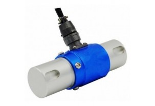

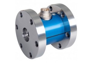
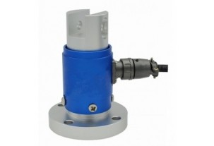
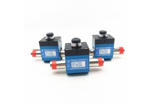
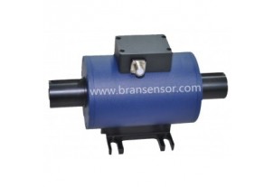
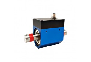
Reaction Torque Sensor With Shaft to Shaft Torque force measurement transducer (BTQ-402)
Read more +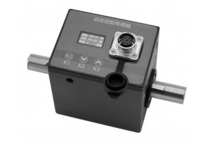
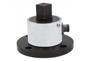
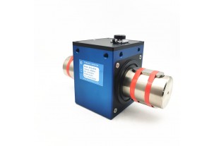
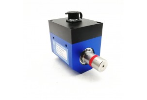
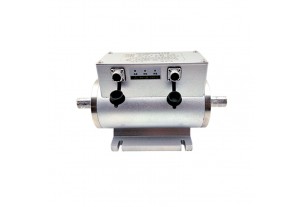
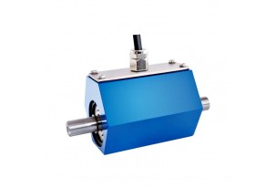
Non-contact Shaft to Shaft Rotary Torque Sensor with Build-in Display to Show Torque, Speed and Power (BTQ-408RTS2)
Read more +
 0086-551-67295053
 info@bransensor.com
 Mon-Sat: 8:30-18:00
 Hefei City, Anhui Province, China


Copyright © 2018 BRANS Measuring & Controlling Technology Co. Ltd


 Pусский
  Español
 ABOUT US